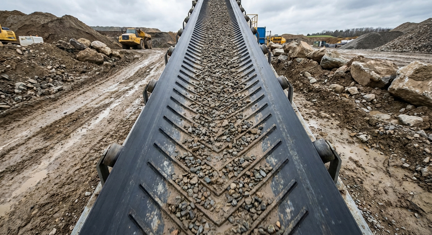
An optimized rubber belt conveyor design improves throughput by balancing tension, load capacity, and durability, reducing downtime and ensuring efficient material handling in industrial systems.
What defines the basics of rubber belt conveyor design?
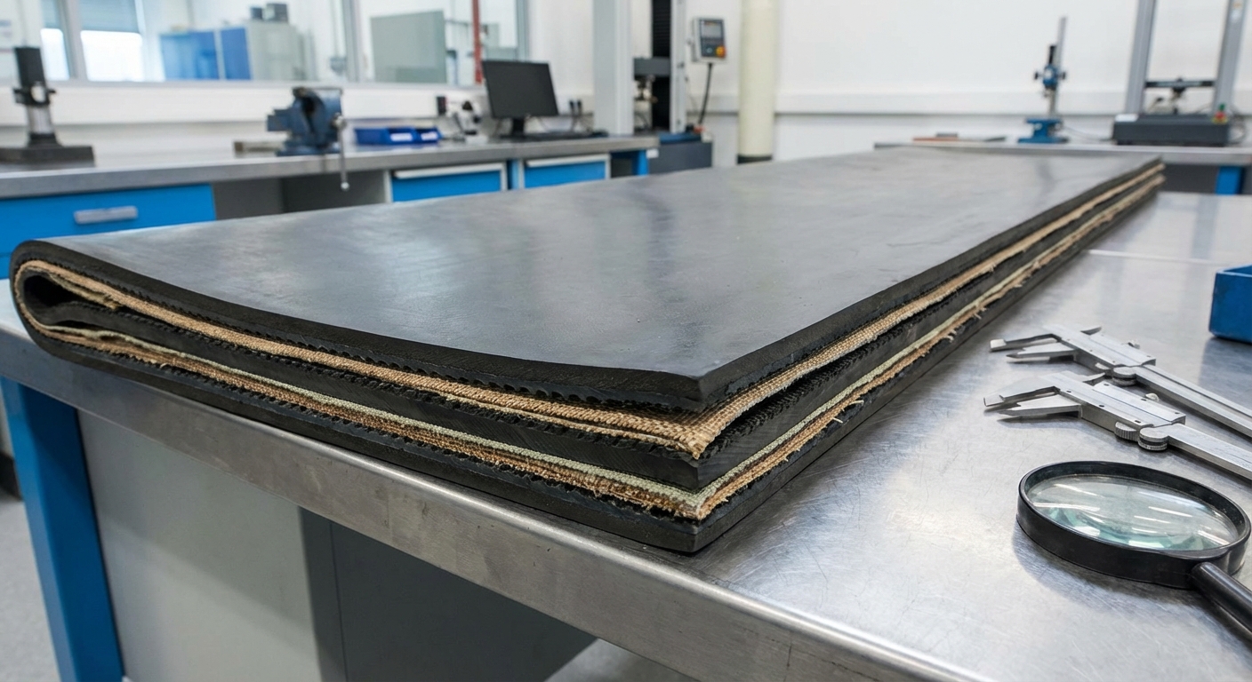
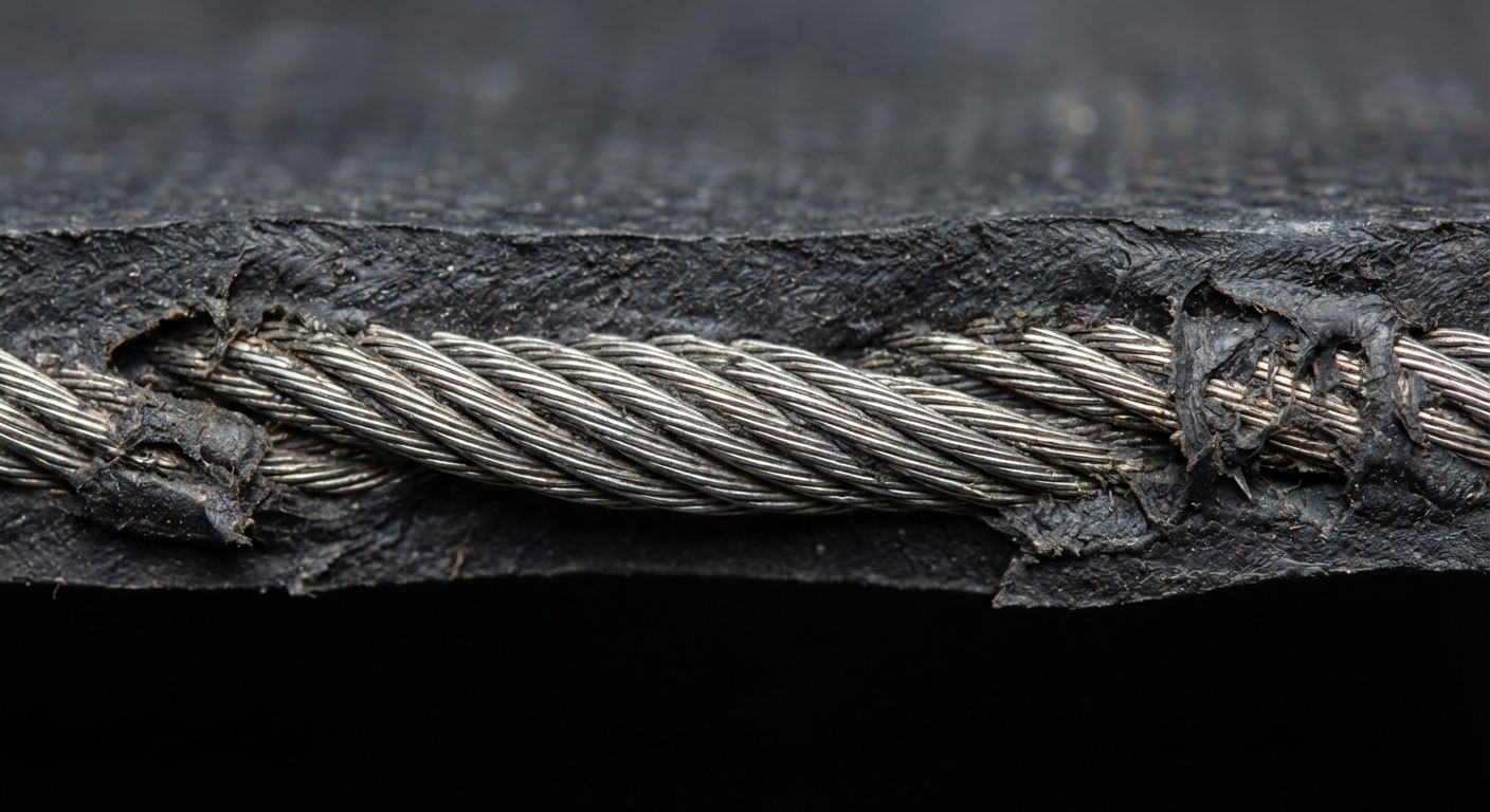
Foundational basics begin with the selection of the carcass material and the chemical composition of the top cover. High-performance rubber belt conveyor design relies on Aramid-reinforced belts or polyester fabrics to provide the necessary tensile strength for heavy industrial loads. These layers ensure the system can withstand the constant pulling forces required for 24/7 throughput.
Engineers must also consider the thickness of the rubber covers to protect the internal carcass from abrasive wear and environmental damage. A well-constructed belt acts as the backbone of your entire material handling operation. By matching the belt’s physical properties to the specific material being moved, you ensure a long service life and minimal stretching.
Understanding the primary system components
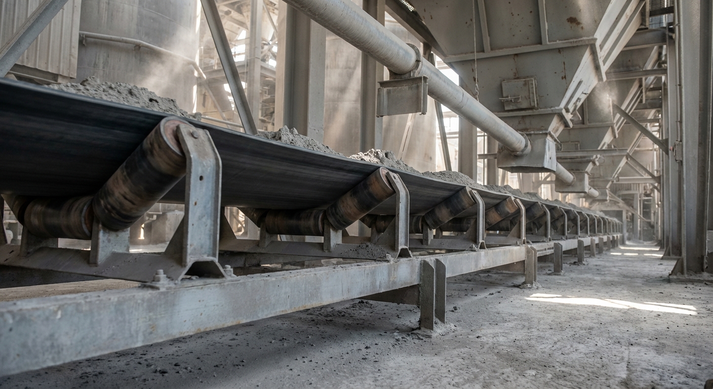
Think about this: your system is only as strong as its weakest component. You must evaluate how the drive pulley, idlers, and take-up assembly interact to maintain a steady flow of material. When you select high-quality components, you reduce the risk of mechanical failure during peak production hours.
- Carcass: The internal reinforcement providing strength.
- Top Cover: The rubber layer protecting against abrasion.
- Pulley: The drum that transmits motive power to the belt.
How do material characteristics influence belt choice?
But that’s not all. You need to analyze the density, lump size, and moisture content of the material you are conveying. If you ignore these variables, you will likely face premature belt degradation or frequent spillage issues. Selecting a rubber compound that resists oil or heat can save you from catastrophic failures.
- Bulk Density: Determines the load weight per linear foot.
- Abrasiveness: Dictates the required hardness of the top cover.
- Temperature: Influences the choice of heat-resistant rubber.
Key Takeaway: Foundational design starts with a deep understanding of how internal reinforcement and external rubber covers work together to support your specific industrial load.
| Component | Function | Design Impact | |
|---|---|---|---|
| Carcass | Tensile Strength | Limits maximum span and lift | |
| Cover | Surface Protection | Determines resistance to wear/heat | |
| Take-up | Tension Control | Prevents belt slippage and sag |
Use this table to evaluate if your current belt’s internal and external layers are matched to your material’s abrasiveness and weight.
How do you calculate volume for rubber belt conveyor design?
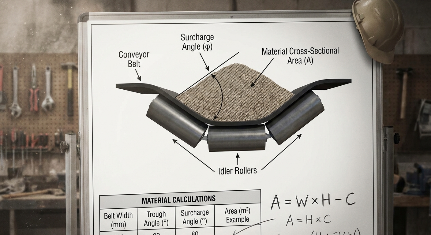
Volume is calculated by determining the cross-sectional area of the material on the belt and multiplying it by the belt speed. In a professional rubber belt conveyor design, you must account for the surcharge angle and the troughing idler configuration to find the maximum possible throughput. This calculation ensures that you are neither underutilizing your equipment nor risking overflow.
Accurate volume modeling prevents the “surge” effect where too much material enters the system at once. By maintaining a consistent speed-to-load ratio, you optimize the energy efficiency of your motors. A standard design usually targets a specific fill percentage to allow for minor fluctuations in material density without causing spillage.
Determining cross-sectional area and surcharge angles
Here is the kicker: the material does not sit flat on the belt. You must understand how the angle of repose affects the “heap” of material as it travels across troughed idlers. If you overestimate the surcharge angle, you will face significant material loss at high speeds.
- Surcharge Angle: The natural angle of the material on a moving belt.
- Trough Angle: The angle of the wing idlers, typically 35 degrees.
- Belt Width: The primary limiting factor for cross-sectional area.
The relationship between belt speed and volume
Now, consider this. You can achieve the same throughput by moving a thin layer of material quickly or a thick layer slowly. You must balance speed against potential component wear, as higher speeds often increase the rate of idler and belt erosion.
- High Speed: Increases throughput but accelerates mechanical wear.
- Slow Speed: Reduces wear but requires wider belts for volume.
- Variable Frequency Drives: Allows you to adjust speed in real-time.
Key Takeaway: Volume capacity is a delicate balance between the belt’s physical trough shape, the material’s surcharge behavior, and the drive speed.
| Factor | Metric | Optimization Goal | |
|---|---|---|---|
| Trough Angle | 20° – 45° | Maximize area without over-stressing belt | |
| Surcharge Angle | Material Specific | Prevent spillage during acceleration | |
| Speed | Meters/Second | Balance volume with idler lifecycle |
Reference this guide to ensure your speed and trough configuration are not exceeding the physical stability of your specific bulk material.
Why is tension critical for rubber belt conveyor design?
Tension is critical because it provides the friction necessary for the drive pulley to move the belt and prevents excessive sag between idlers. A robust rubber belt conveyor design often utilizes Steel Cord Conveyor Belts to handle the immense effective tension (Te) required for long-distance or high-lift mining applications. Without proper tension, the belt will slip on the drive pulley, causing heat damage and system failure.
Engineers must calculate the tight-side (T1) and slack-side (T2) tensions to ensure the belt remains seated and stable. Proper tensioning also reduces the power consumption of the motors by minimizing the energy lost to belt deformation. When tension is perfectly calibrated, the entire system operates with a rhythmic efficiency that maximizes daily throughput.
Calculating effective tension for drive power
But that’s not all. You must sum the forces required to overcome idler resistance, lift the material, and accelerate the load from a standstill. When you calculate Te accurately, you can select a motor that provides exactly the right amount of horsepower without over-investing in unnecessary capacity.
- Lift Resistance: The force needed to move material vertically.
- Friction Resistance: Resistance from idlers and pulleys.
- Acceleration Force: Tension required to reach operating speed.
Managing slack-side tension to prevent slippage
It gets better. You can utilize gravity take-up towers or hydraulic winches to maintain constant tension even as the belt stretches under load. When you control slack-side tension, you eliminate the vibrating “waves” that can cause material to bounce off the belt.
- Gravity Take-ups: Automatically adjust to belt elongation.
- Screw Take-ups: Best for short systems with minimal stretch.
- Slip Detection: Sensors that stop the motor if tension drops.
Key Takeaway: Precise tension management ensures the belt transmits power efficiently while maintaining the structural integrity of the carcass under heavy loads.
| Tension Type | Calculation Focus | Operational Benefit | |
|---|---|---|---|
| Effective (Te) | Total Resistance | Optimal motor sizing | |
| Tight Side (T1) | Maximum Load | Prevents belt snapping | |
| Slack Side (T2) | Drive Friction | Stops pulley slippage |
Analyze your tension values to identify if your drive slippage is caused by insufficient slack-side weight or an undersized motor.
How do materials impact rubber belt conveyor design?
Materials impact design by dictating the tensile strength requirements and the chemical resistance needed for the belt’s surface. In any high-load rubber belt conveyor design, the choice between synthetic fibers and steel cord reinforcement depends entirely on the distance and vertical lift of your system. Choosing the wrong material can lead to excessive elongation, which requires frequent take-up adjustments and causes tracking issues.
Specialized rubber compounds are engineered to handle extreme conditions like sub-zero temperatures or hot clinker in cement plants. If you are moving heavy ores, you need a high-impact carcass that can absorb the energy of falling rocks at transfer points. The synergy between the internal reinforcement and the external rubber determines the ultimate durability of your throughput engine.
The benefits of synthetic reinforcement
Wait, there is more. You should consider polyester (EP) or nylon fabrics if your application requires high flexibility and resistance to moisture. When you use synthetic carcasses, you gain a belt that is lighter and easier to install than steel cord alternatives, making it ideal for shorter plant conveyors.
- EP Fabric: Offers low elongation and high impact resistance.
- Nylon: Provides excellent troughability and elastic recovery.
- Flexibility: Allows for smaller pulley diameters in tight spaces.
When to choose steel cord for heavy lift
The best part? You can transport thousands of tons over several kilometers with almost zero belt stretch if you select steel cord reinforcement. You will find that these belts are the standard for high-capacity mining because they offer the highest safety factors for deep-shaft or overland systems.
- Low Stretch: Minimizes the need for long take-up travel.
- High Strength: Handles the highest tensions in the industry.
- Longevity: Steel cords are protected from corrosion by thick rubber.
Key Takeaway: Your choice of carcass material—whether fabric or steel—must be dictated by the calculated maximum tension and the environmental stresses of your facility.
| Reinforcement | Best Application | Primary Strength | |
|---|---|---|---|
| Polyester (EP) | General Industrial | Moisture and rot resistance | |
| Steel Cord | Mining & Overland | Ultra-low elongation | |
| Aramid | Impact Heavy | High strength-to-weight ratio |
Use this table to decide if your current fabric belt should be upgraded to steel cord for better tension stability on long runs.
Can idler spacing improve rubber belt conveyor design?
Idler spacing improves design by minimizing belt sag and reducing the energy required to move the load. In a professional rubber belt conveyor design, you can implement Sidewall Conveyor Belts or standard troughed idlers spaced according to CEMA standards to ensure the belt remains properly supported. If idlers are spaced too far apart, the belt will sag, creating “humps” that increase rolling resistance and power consumption.
Closer spacing is generally required at loading points where the material’s impact is greatest. By optimizing the distance between these rollers, you distribute the weight evenly, which prevents the rubber from being pinched or damaged. Well-maintained idlers also assist in keeping the belt centered, which is vital for maintaining high-volume throughput without interruption.
Optimizing idler spacing for heavy load support
Listen to this: if you reduce belt sag to under 2%, you will see a noticeable drop in your monthly energy bills. You must adjust your spacing based on the tension at that specific point in the conveyor run; areas of lower tension require more frequent idler support.
- Carrying Idlers: Support the loaded belt every 1.0 to 1.5 meters.
- Return Idlers: Support the empty belt every 3.0 meters.
- Variable Spacing: Tighter near the tail, wider near the head.
Where to place impact idlers for protection
Think about this: the most damage to your belt occurs at the loading zone. You must install heavy-duty impact idlers with rubber cushioning to absorb the shock of falling material. When you protect the belt at the source, you extend its overall lifespan significantly.
- Rubber Disks: Provide a cushion against heavy lump impact.
- Reinforced Frames: Support the extra weight of the loading zone.
- Slider Beds: An alternative for very high-impact areas.
Key Takeaway: Strategic idler placement balances the need for load support with the goal of minimizing friction and energy loss across the system.
| Idler Type | Common Spacing | Critical Goal | |
|---|---|---|---|
| Troughing | 1.2m – 1.5m | Prevent sag and spillage | |
| Impact | 0.3m – 0.6m | Absorb loading energy | |
| Training | Every 15m – 30m | Correct belt misalignment |
Check your loading zone spacing; if you see the belt dipping significantly between rollers, your idlers are likely too far apart.
Does lagging enhance rubber belt conveyor design?
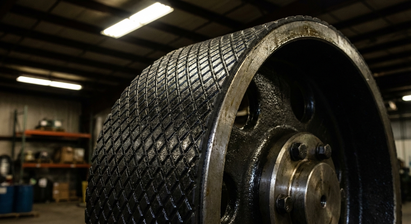
Lagging enhances design by increasing the coefficient of friction between the drive pulley and the belt surface. A high-efficiency rubber belt conveyor design utilizes diamond-patterned or ceramic lagging to ensure that power is transmitted without slippage, even in wet or muddy conditions. Without this protective layer, the bare metal of the pulley would quickly wear down and lose its grip on the rubber belt.
High-quality lagging also acts as a wear-shedding surface that prevents material buildup on the pulley face. This is essential for preventing belt tracking issues caused by uneven diameters on the drum. By choosing the right lagging material, you ensure that your drive system remains reliable during heavy rains or high-humidity shifts.
Comparing friction coefficients of different surfaces
But that’s not all. You need to understand that plain rubber lagging offers a different grip level compared to ceramic inserts. When you select ceramic lagging, you gain a friction coefficient that is nearly double that of bare steel, allowing for lower overall system tension.
- Plain Rubber: Good for dry, light-duty applications.
- Diamond Pattern: Channels water away to maintain grip in the rain.
- Ceramic Inserts: Provides the highest grip and wear resistance.
Benefits of ceramic lagging for high-tension drives
Now, consider this. You can drastically reduce your take-up weight requirements if you switch to ceramic lagging on your primary drive pulley. When the lagging “bites” into the bottom cover of the belt, it prevents hydroplaning and ensures the belt stays in motion under full load.
- Extreme Grip: Prevents slippage in the worst environmental conditions.
- Heat Dissipation: Reduces the thermal stress on the belt’s bottom cover.
- Durability: Lasts much longer than traditional rubber lagging.
Key Takeaway: Pulley lagging is a low-cost investment that significantly boosts drive efficiency and protects the expensive belt carcass from friction-based heat damage.
| Lagging Type | Friction Level | Ideal Environment | |
|---|---|---|---|
| Bare Steel | 0.15 | Not recommended for drives | |
| Diamond Rubber | 0.35 | Wet or outdoor plants | |
| Dimpled Ceramic | 0.50+ | High-tension mining drives |
If you are experiencing pulley slippage during start-up, evaluate if your lagging has worn smooth or needs to be upgraded to ceramic.
Why use cleated styles in rubber belt conveyor design?
Cleated styles are used to move bulk materials up steep inclines where gravity would otherwise cause the load to slide backward. In an advanced rubber belt conveyor design, integrating Chevron Conveyor Belts allows for transport angles of up to 40 degrees, which is double the capacity of a smooth belt. These molded patterns provide the mechanical “bite” necessary to hold loose or wet materials in place.
Cleats are especially valuable in facilities with limited floor space where vertical lift is required. By moving material at steeper angles, you can reduce the overall length of the conveyor structure, saving on both footprint and capital costs. Whether you are moving grain, sand, or coal, cleated designs ensure your throughput remains consistent regardless of the slope.
Designing for vertical lift with specialized belts
It gets better. You can utilize corrugated sidewalls and transverse cleats to move materials vertically at 90-degree angles. When you use this configuration, you eliminate the need for multiple transfer points and complex bucket elevators, streamlining your entire production flow.
- Sidewalls: Contain the material laterally to prevent side-spillage.
- Cleats: Act as “buckets” to carry the material upward.
- Base Belt: Usually cross-rigid to prevent bowing on the return side.
Selecting the right cleat profile for bulk materials
Wait, there is more. You must choose between different cleat heights and shapes based on the size of the material you are conveying. If you use cleats that are too small for large rocks, the material will simply tumble over them, causing a dangerous avalanche on the belt.
- T-Cleats: Best for small, granular materials like sand.
- C-Cleats: Designed for wet materials that might stick to the belt.
- Chevron Patterns: Ideal for steep inclines without full vertical lift.
Key Takeaway: Cleated and sidewall designs allow you to maximize your facility’s vertical space while preventing material rollback on steep inclines.
| Feature | Design Purpose | Vertical Benefit | |
|---|---|---|---|
| Chevron Pattern | Moderate Incline | Increases angle from 20° to 40° | |
| Sidewall + Cleat | Steep/Vertical | Enables 90° vertical transport | |
| Cross-Rigidity | Structural Support | Keeps belt flat on return idlers |
Assess your plant’s footprint; if you are using long, low-angle conveyors, a cleated belt could save significant floor space.
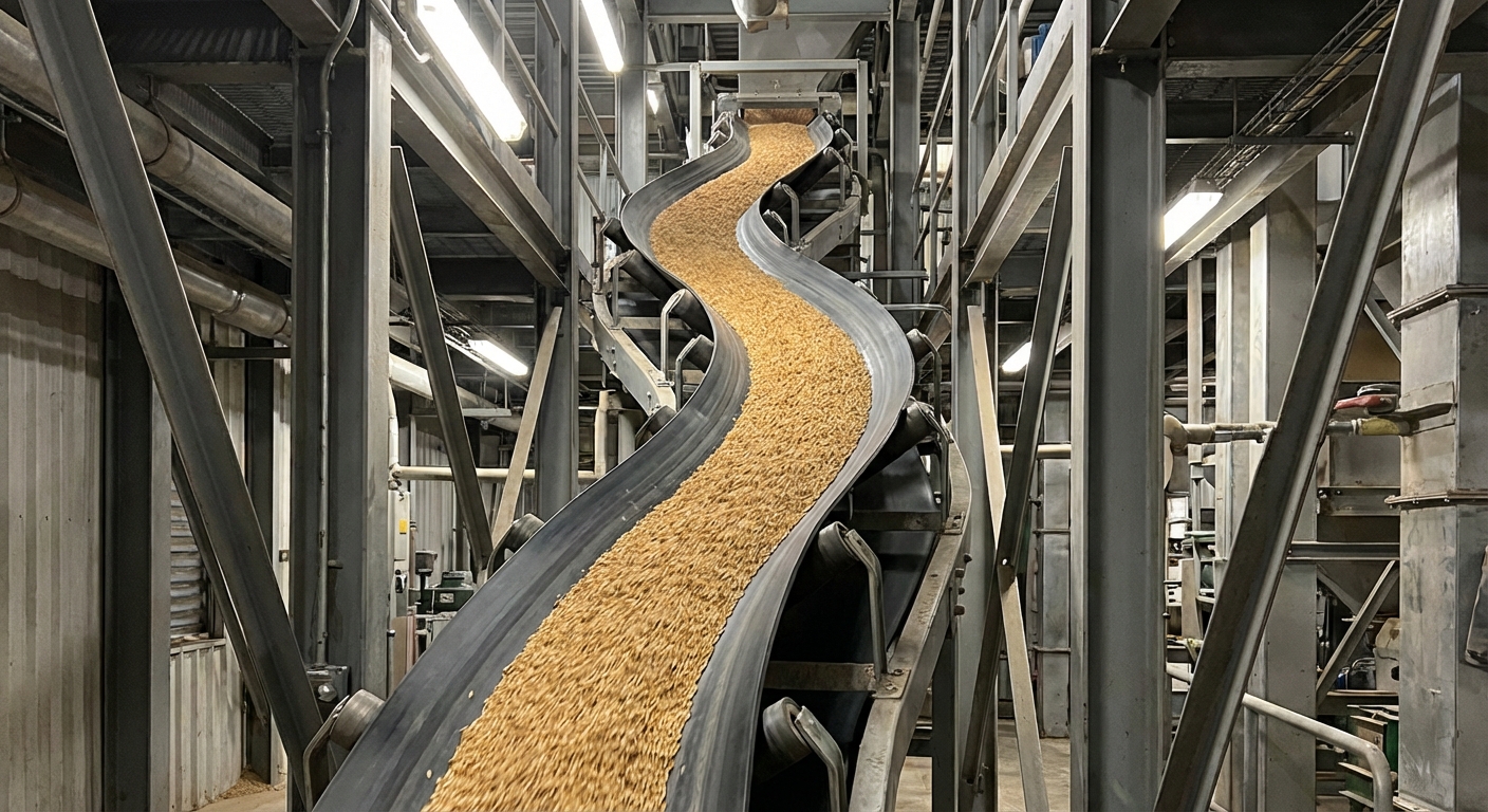
How do patterns optimize rubber belt conveyor design?
Patterns optimize design by enhancing the grip on the material surface and improving drainage in wet applications. A high-performance rubber belt conveyor design uses specifically molded chevron or V-shapes to trap small particles and prevent them from sliding down the belt. This optimization is vital for construction and aggregate sites where material is often damp and prone to shifting.
Patterned belts also help distribute the material evenly across the width of the belt, which improves balance and tracking. By maintaining a uniform load distribution, you reduce the strain on the idlers and pulleys. These textures essentially turn a flat transport surface into a high-traction road for your industrial bulk goods.
Angle of repose and the limits of smooth belts
Here is the kicker: a smooth belt loses efficiency as soon as the incline exceeds 15 to 18 degrees. You must understand that once the conveyor angle nears the material’s angle of repose, your throughput will drop to zero without a patterned surface.
- Static Friction: The grip a smooth belt has on dry material.
- Mechanical Grip: The physical hold a pattern provides on wet loads.
- Safety Margin: Patterns prevent sudden material slides during stops.
Why use patterned belts for wet loads?
Think about this: water acts as a lubricant on a smooth rubber belt, causing sand or slurry to wash away. You should use open chevron patterns to allow excess water to drain off the sides while the solid material remains trapped within the V-shape.
- Drainage: Prevents water from pooling in the middle of the belt.
- Traction: Maintains throughput in heavy rain or wash-down areas.
- Self-Cleaning: Patterns are designed to flex and shed sticky material.
Key Takeaway: Molded patterns extend the functional range of your conveyor, allowing for reliable operation in wet conditions and steeper-than-normal angles.
| Pattern Type | Height Range | Best Material | |
|---|---|---|---|
| Open V | 5mm – 15mm | Sand, small aggregates | |
| Closed Chevron | 15mm – 32mm | Large coal, wet minerals | |
| U-Shape | Variable | Grains and agricultural goods |
If your material slides back during incline transport, your current belt pattern is likely too shallow for the surcharge angle.
Are enclosed systems part of rubber belt conveyor design?
Enclosed systems are a specialized part of design used for environmental protection and dust containment. In modern rubber belt conveyor design, implementing Pipe Conveyor Belts allows you to roll the flat belt into a tubular shape, sealing the material inside. This is the ultimate solution for transporting dusty materials like cement or chemicals through sensitive or populated areas.
Enclosed belts also protect the material from external elements like rain and wind, which is crucial for maintaining the quality of sensitive bulk goods. Because the belt is rolled into a pipe, it can navigate tighter horizontal and vertical curves that a traditional trough belt cannot handle. This flexibility allows engineers to design paths that snake around existing infrastructure.
Environmental protection with pipe systems
But that’s not all. You can eliminate the need for expensive dust collection systems at every transfer point by keeping the material sealed within the belt itself. When you prevent spillage and dust emissions, you comply with strict environmental regulations and improve the air quality of your facility.
- Zero Spillage: Material is completely enclosed during transport.
- Weatherproof: Prevents moisture from changing material weight.
- Dust Control: Keeps fine particles from escaping into the air.
Now, consider this. You don’t have to build straight lines between your loading and discharge points if you use a pipe system. You gain the ability to curve the conveyor around buildings or natural obstacles, which can significantly reduce the cost of land acquisition and civil engineering.
- Narrow Footprint: Pipe belts take up less lateral space.
- High Curvability: Can handle much tighter radii than troughed belts.
- Stability: The tubular shape is inherently more stable in high winds.
Key Takeaway: Enclosed pipe systems are the premier choice for facilities requiring absolute dust containment and the ability to navigate complex, curved transport paths.
| Advantage | Engineering Detail | Operational Impact | |
|---|---|---|---|
| Containment | Enclosed “O” shape | No environmental contamination | |
| Flexibility | Tight horizontal curves | Simplified site layout | |
| Protection | Sealed transport | Prevents material contamination |
Evaluate a pipe belt transition if your current open-trough system is causing environmental complaints or significant dust loss.
How do you track a rubber belt conveyor design?
Tracking is managed by ensuring the pulleys are perfectly aligned and the tension is distributed evenly across the belt width. In any successful rubber belt conveyor design, you must utilize training idlers and adjustable take-up frames to correct any drift that occurs during operation. If a belt is not tracking correctly, it will rub against the structure, destroying the belt edges and risking a total system shutdown.
Modern systems often include automatic tracking sensors that provide real-time feedback to the control room. By maintaining a perfectly centered belt, you ensure that material is loaded exactly in the middle of the trough, which further stabilizes the system. Precision alignment is the final step in transforming a collection of parts into a high-efficiency throughput engine.
The critical role of the take-up assembly
Listen to this: the take-up is the lungs of your conveyor system. You must ensure it has enough travel to account for initial belt stretch and thermal expansion throughout the year. If your take-up is stuck or bottomed out, your belt will lose tension and wander off the center line immediately.
- Gravity Towers: Provide constant, self-adjusting tension.
- Screw Frames: Require manual adjustment but are compact.
- Alignment: Ensure the take-up pulley is perfectly square.
Utilizing skirting for material containment
The best part? You can prevent material from jamming your idlers by installing high-quality rubber skirting at all loading and transfer points. When you keep the belt path clear of debris, you eliminate the most common cause of belt misalignment and premature wear.
- Soft Rubber Skirts: Seal the gap between the chute and the belt.
- Adjustable Clamps: Allow for easy maintenance as the rubber wears.
- Internal Liners: Protect the skirting from the direct impact of the load.
Key Takeaway: Effective tracking is a combination of mechanical alignment, consistent tensioning, and proactive cleanliness at all loading points.
| Method | Component | Result | |
|---|---|---|---|
| Mechanical | Training Idlers | Automatic drift correction | |
| Tensioning | Gravity Take-up | Constant tension for stability | |
| Sealing | Rubber Skirting | Prevents debris from de-tracking |
If your belt is fraying at the edges, check your training idlers first; they are the frontline defense against structural damage.
Strategic Success in Conveyor Engineering
Mastering conveyor design is an iterative process of balancing load, tension, and environmental resilience. By addressing bottlenecks at the design phase—such as improper carcass selection or insufficient idler support—you transform a potential liability into a reliable engine of throughput. We have explored how specialized reinforcements, molded patterns, and advanced tracking mechanisms work in unison to eliminate the costs of unexpected downtime.
Our vision for the industry is one where every material handling system operates at peak efficiency with minimal environmental impact. We are committed to providing the durable components and engineering insights required to scale your production safely and sustainably. For expert guidance on optimizing your specific system or to request a custom quote, contact us today and let our four decades of manufacturing expertise power your facility’s future.
Expert Insights: Frequently Asked Questions
Can I use chevron belts for wet or slurry-like materials?Yes, but you must select an open chevron pattern to ensure proper drainage. While the patterns provide mechanical traction that prevents the solids from sliding, the open channels allow water to escape so the load doesn’t become a liquid slurry that overflows the belt.
What’s the best way to determine if I need steel cord or EP fabric?Calculate your maximum operating tension (T1) and the total conveyor length. If your system is over 500 meters long or requires a high safety factor that would make a fabric belt too thick to wrap around standard pulleys, steel cord is the superior and more reliable choice.
How do I know if my idler spacing is causing excessive energy loss?Observe the belt sag between the carrying idlers when the system is fully loaded. If the sag exceeds 2% of the distance between idlers, the material is essentially being “pushed uphill” over every roller, which significantly increases rolling resistance and your electricity costs.
Can I retrofit an existing troughed conveyor into a pipe system?Generally no, because pipe conveyors require specific hexagonal idler arrangements and a belt carcass with high transverse flexibility. Attempting to force a standard troughed belt into a pipe shape will likely lead to carcass cracking and severe tracking failures.
What’s the best lagging material for a high-moisture environment?Ceramic lagging with dimpled inserts is the gold standard for wet or muddy conditions. The hard ceramic dimples physically bite into the bottom cover of the rubber belt, providing a mechanical lock that prevents the hydroplaning common with plain rubber or bare steel pulleys.